Dual Garbage Bin Transporter
projectsparentsHere's a quick post on a garbage bin transporter I made for my parents to help them transport their bins down their gravel driveway. I was dissatisfied with existing devices because they either required lifting the entire bin by yourself or left the bins in contact with the ground, limiting turning/backing up and de-facto requiring a smooth driveway.
So the basic goals were to:
- attach to the 2" hitch receiver on a truck
- lift the bins off of the uneven, angled, snowy, muddy ground
- be installable and operable by my mother
- be light and simple enough that it can be removed from the receiver when not in-use
- be easily constructed, maintained, and fixed
- be cheap
- no modification to the bins
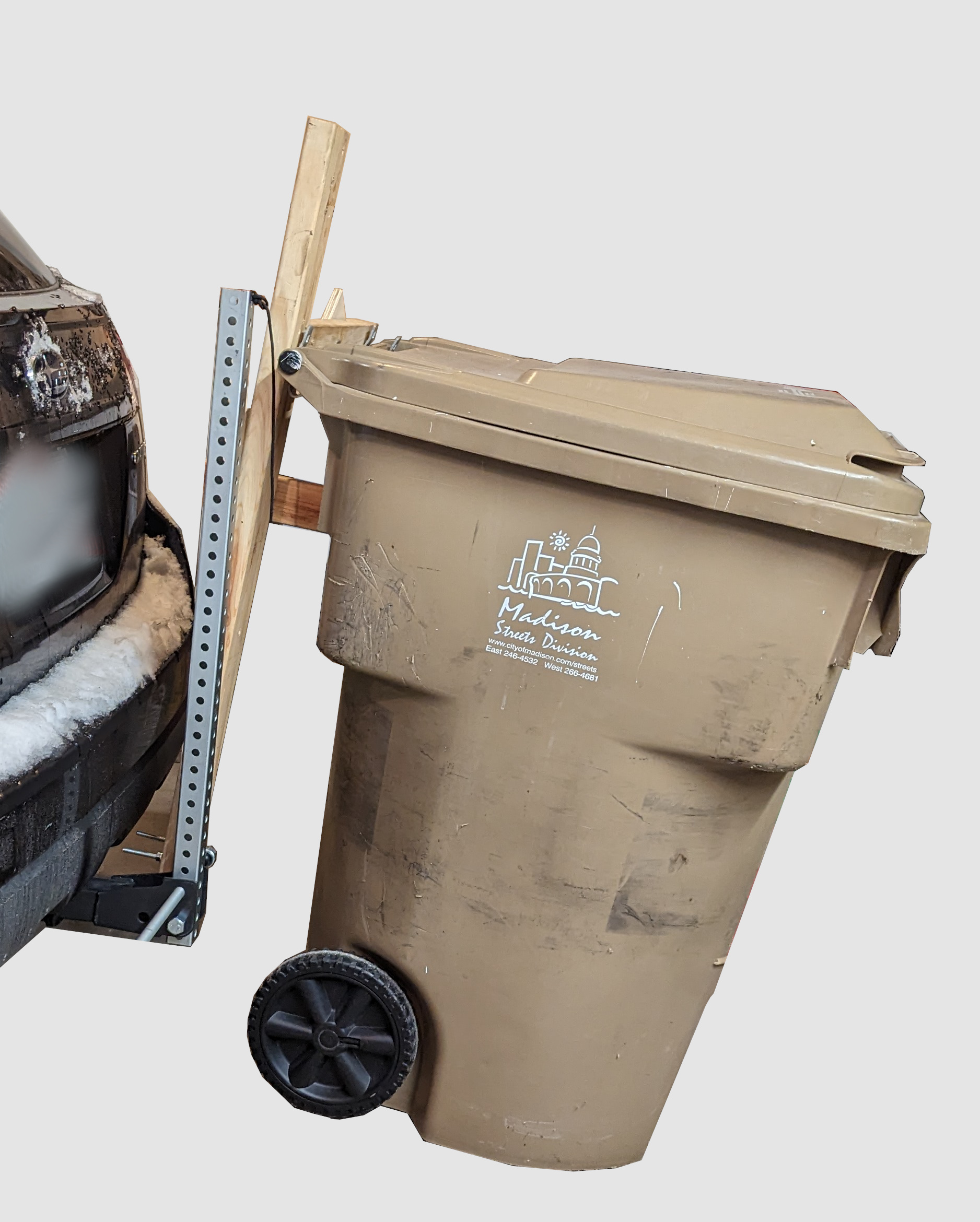
And here's what I came up with:
It uses a steel hitch adapter, mast, and horizontal bar to raise two full-size garbage bins approximately 8" off of the ground. On each arm a large tongue engages the dumpster's standard lift cavity, under which is a vertical panel to control the orientation of each bin. Lifting each bin is a 8:1 pulley system, which for a 60lbf bin leads to approximately 20lbf pull force on the rope. The overall assembly weighs approximately 30lbf, right at the edge of what is reasonable.
Arm Design
Garbage bins are rather big and bulky, and I considered three different arm designs in my attempt to limit mass and complexity.
The first attempted to interface with the bin handle. The implicit question was whether I could avoid an explict actuation mechanism and instead (politely) ask Mom to push the bin against the vehicle, with the arm lifiting it off the ground. While simple, this suffered from a poor hinge design, insufficient space between the arm and vehicle for the lock/actuation mechanism, and, with such a high attachment point preferred the arm to be substantially vertical which left it little angle to raise the bin off the ground.
I considered a 'blade' concept, where the arm would engage the side flange at the top of the bin:
This kept the hinge near the hitch and the arm small, though at the cost of a significant twisting moment on the arm and hinge. I was not at all confident that I could make the hinge attachment and vertical 'blades' strong enough to survive the loads of the bumpy driveway. If I was able to work aluminum in the garage this might have worked out well. This quick prototype also showed that getting the blades to engage with the flange required relatively precise positioning, ~1" forward/back and 1/2" side-to-side, that made this variant appear frustrating to use.
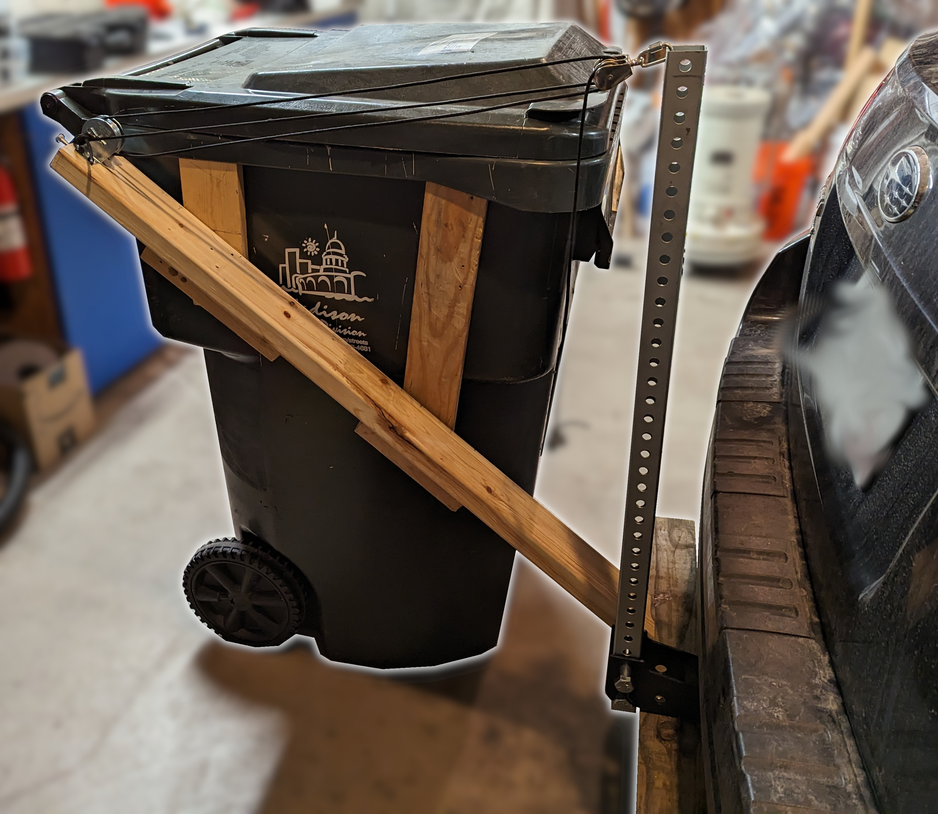
Finally, I gave in and designed an arm to engage the same features that the garbage trucks do, the bar and pocket on the street side of the bin. As this results in a much shorter arm, I was reluctant to give up the free mechanical advantage...but I was eventually able to make it up in the pulley system. Being roto-molded, everything on the bin is angled in some way or another, making measurement annoying. While I trusted that my garbage bin was similar to my mother's in the basic interface, I wanted to be able to modify the engagement features when I was on-site, hence this has a somewhat elaborate plywood tongue and bracing that are easily disassembled.
Actuation
I wanted to avoid using a powered actuator for the complexity and mass, leading me to look at ratchet straps. Unfortunately, these act in only a single direction and I wanted the mechanical advantage for both raising and lowering. Tackles and winches are reversible but I could not find any small enough for this application. I also didn't trust my 3D printing to design a version of either of these, fearing they would have too many parts and failure paths.
Windlass
I very much wanted to use a windlass/differential chain hoist and came close to designing one to use ball chain, but since these require a continuous loop of chain, I was concerned about trusting the connection in a spliced ball.
Following this I designed and printed windlass, in which a length of rope is wound around two pulleys of differing sizes such that when they rotate the rope is played out and taken up at different rates, leading to a significant advantage. This was the first prototype of this project and so I didn't have a good estimate of the bin weight or arm design, with the hard implication that I didn't know the winch mounting, loading, actuation distance, or how the line of actuation would change during operation. Though it developed the desired mechanical advantage, my prototype was rather too large and difficult to flexibly mount.
Pulley System
Next, I fell back to a compound pulley system, though instead of going for a standard, parallel pulley block I though it would be interesting to try a circular arrangement:
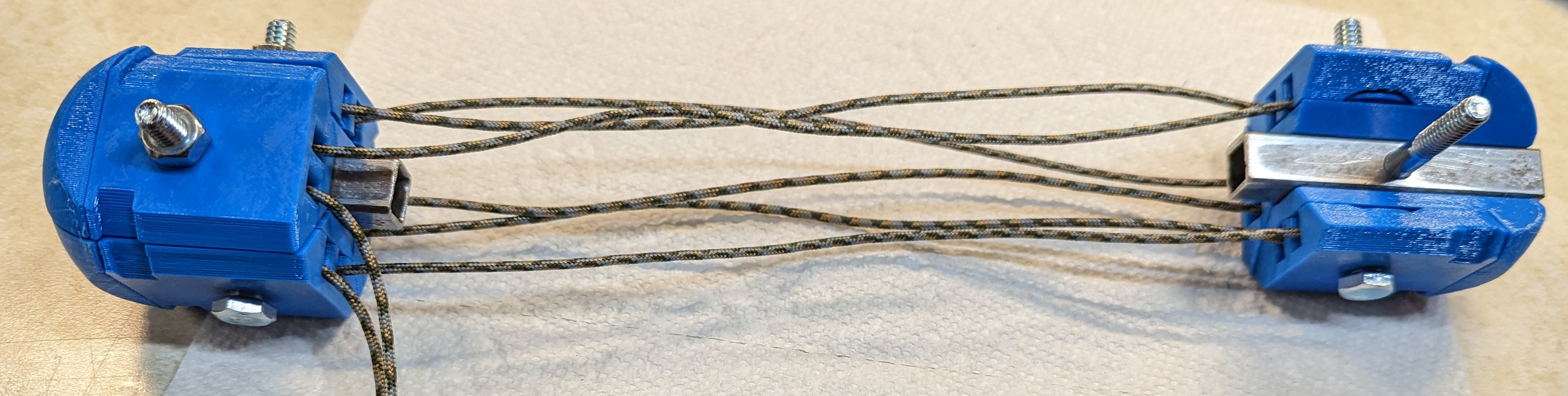
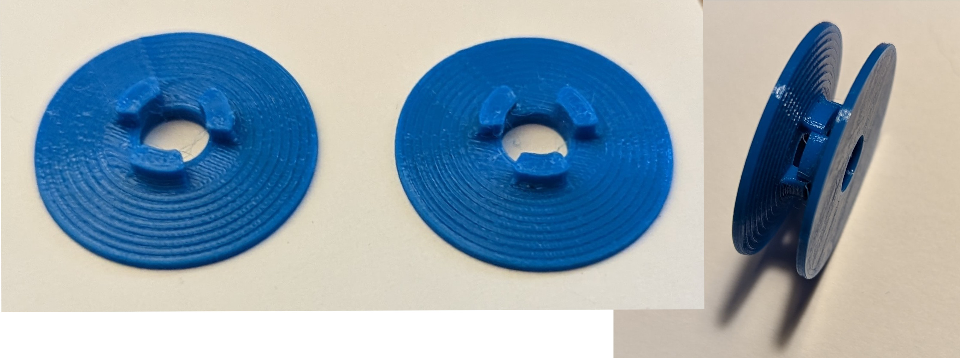
Above the pulley axel bolts is a 10mm groove to attach the ends of a fabric tube that would enclose the rope and keep everything looking neat. Unfortunately, it experienced significant friction in the plain (journal) bearings of 3D printed pulleys which totally undermined the function, to the point that some of the inner rope runs would not move under appreciable loads. This friction also concentrated the rope loading on one side or corner of the blocks, tilting each and applying loads to the sides of the pulleys which lead to their separating. It would have been good to do a little pre-design calculation here.
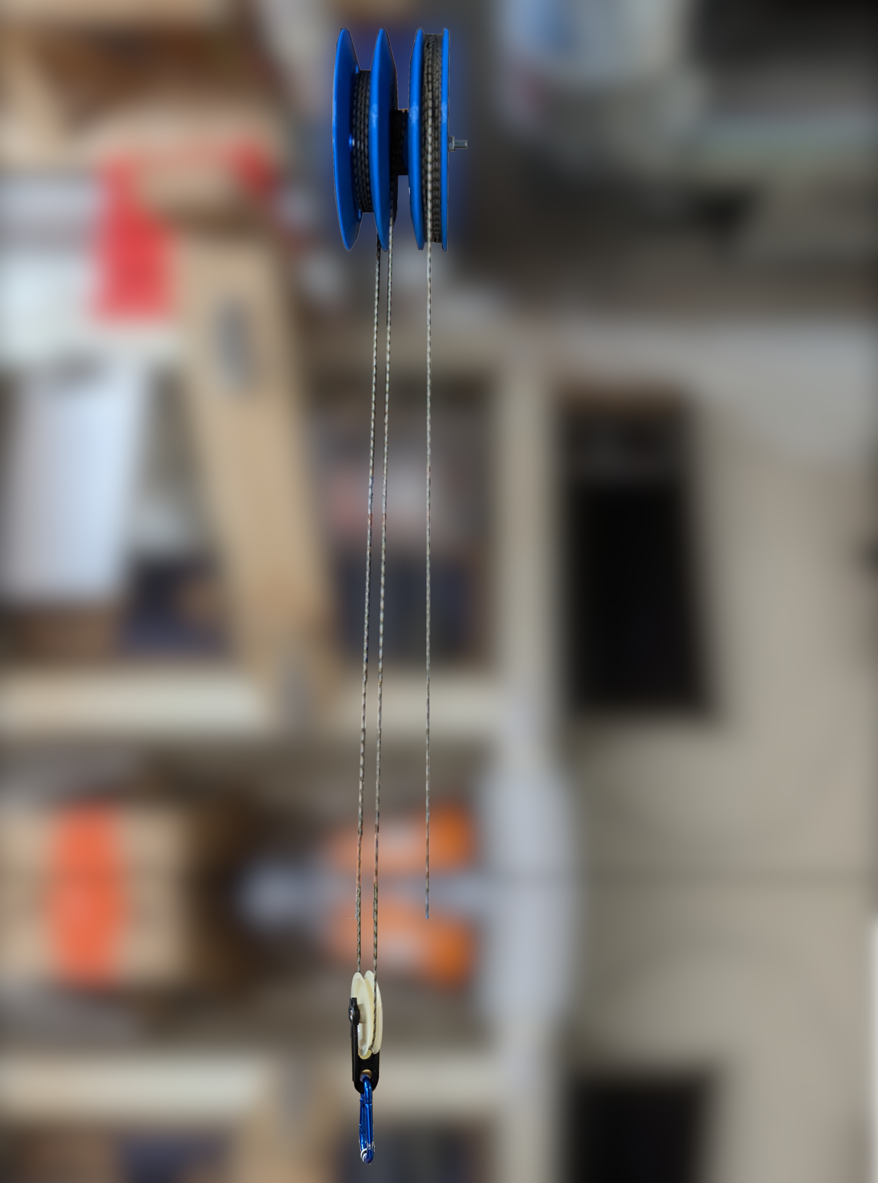
With that, I reverted to a standard parallel pulley block design off of some ball-bearing pulleys I'd used before. They're actually rollers for sliding doors, with the effect that they have shallower grooves with a circular profile, but they work well enough here. And since I was heading to Menards, I bought some 3/4" aluminum flat bar for the load-bearing side plates.
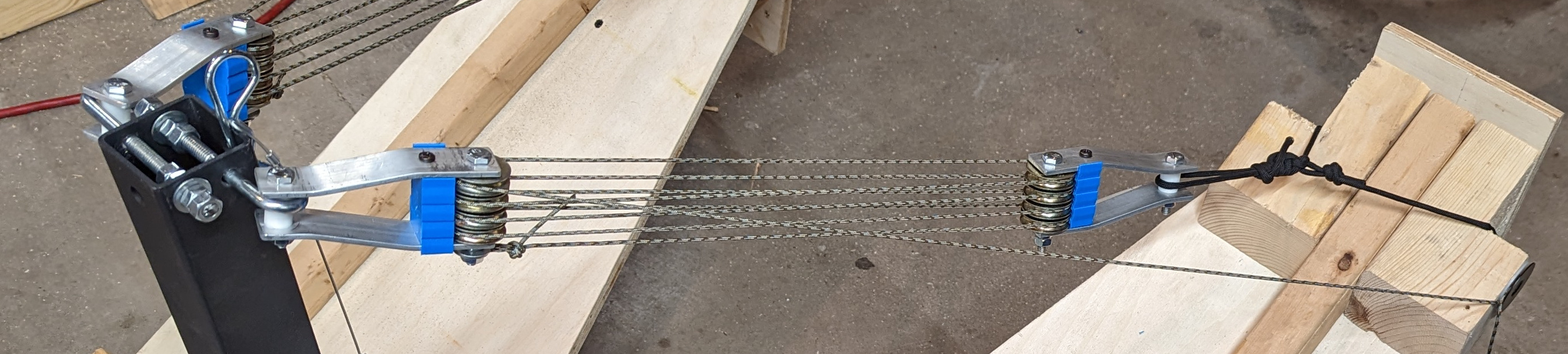
Between the pulley axel bolt and the attachment bolt, I added some 3D-printed rope guides to try to prevent the rope from jumping out of the pulley grooves when unloaded. With 4 pulleys on each side and the rope terminated to the truck-side of the arms, the rope makes 8 turns over the pulley system. Even with the ball-bearing pulleys, pulley friction still arises, unevenly loading the rope turns which leads to some angling of the blocks during actuation.
Each of the blocks are attached to a two-axis pivot; on the mast the J-bolts are free to rotate in their hole and the pulley block within the J, and on the arm side the rope attachment permits a similar motion. Both of these allow the pulley system to act along the ideal line of action.
Use
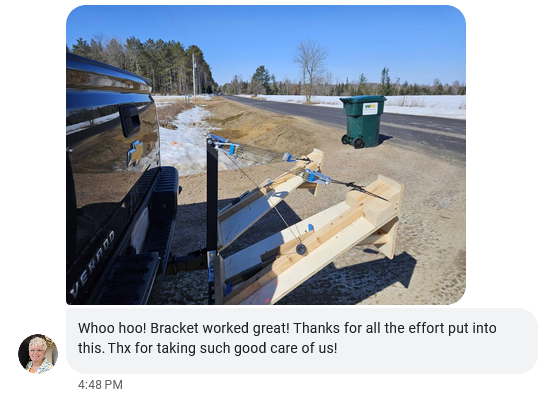
It was approximately 10°F and sunny the day I tested it and gave it to my mother. The arms and tongues engage the dumpsters well, easily and stably lifting the bins off of the ground.
On-site, it became clear that my disc-based rope clamp was very awkward and also that additional leverage was needed. Lacking tools and time, I vaguely recalled the two-handed winch used on some sailboats and thought of a simple two-bar crank:
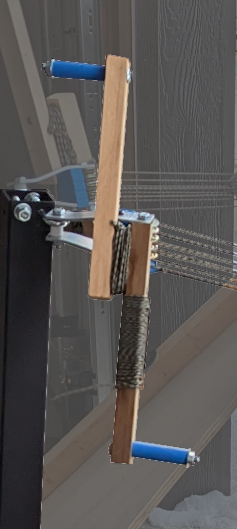
The rope winds on a 'pulley' of approximately 4" diameter, turned by crank handles that are 8" from the center of rotation, providing a 2x advantage. It requires a bit of practice to coordinate the motion of your hands when the rope is loaded, but all accounts are that it works well enough.
This will break some day, perhaps then I'll have a TIG welder and can remake it in aluminum...
- Next: Improving Freight Trains
- Previous: The Heroic Age of American Invention